Break down on how to read the performance chart and test methods
Tip load
Tip load is the numerical conversion of the physician's feeling of "softer/stiffer" of the wire tip, and is calculated by its gram value.
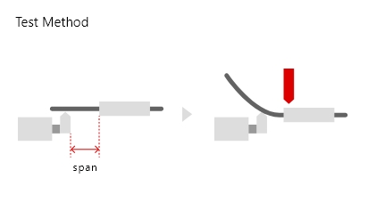
Test Method
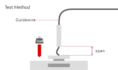
Measured by the force needed to bend guide wire wet with water pushed against a sensor 10mm from the tip.
Guide wires with high tip load have…
- Thick cores and high torque force
- Low in tip flexibility and tend to run straight
Guide wires with low tip load have…
- Thin cores and low torque force
- High in tip flexibility and tend to change direction according to the resistance from vessels and lesions
Tip end design
The ball tip attached to the tip of the guide wire are processed at the manufacturing sites, and contribute to perfomance in penetration force of each wire.
-
Round tip
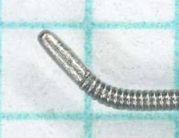
Standard round ball-tip design. -
Micro-cone tip
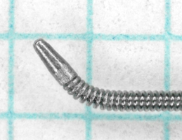
The end of the ball tip is grinded to form a cone-shape, which enhances its ability to penetrate lesions. -
Blunt tip
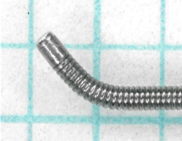
The tip is processed to form a blunt, square-like shape which increases contact area against the lesion and resistance to the tip. In cases where the vessel route is unclear, the risk of perforation can be reduced as the wire can be advanced according to feedback from the tip.
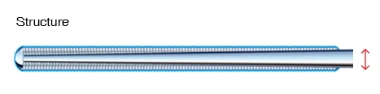
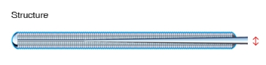
Coil design
The O.D. of the tip of the coil. ASAHI coil forming technologies makes it possible to adjust the O.D. to fit the features of each guide wire.
-
Straight
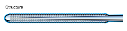
Standard design where the coil maintains a fixed O.D. -
Tapered coil
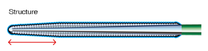
The O.D. becomes smaller toward the tip. This design enhances the wire's ability to enter CTO lesions and select smaller routes
Lubricity
Ability to lower the resistance felt from the vessel or lesion when advancing the guide wire. The effects change according to the coating material.
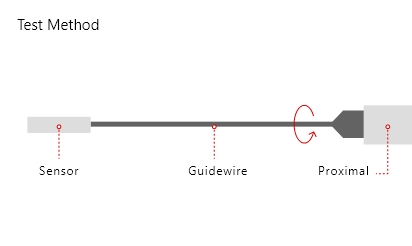
Test Method

Measured by the resistance when the guide wire is pushed back and forth with a weight on it.
Three coatings
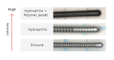
When the lubricity is high…
- It is easier to advance through tighter routes because of less resistance from the vessel and lesion.
- There is a higher possiblity of the wire tip to move unintentionally due to cardiac beating.
Torque response
The ability to quickly transmit the rotation applied at the proximal side to the tip of the wire. The quicker the rotation is transmitted to the tip, the higher the torque response.
Test Method
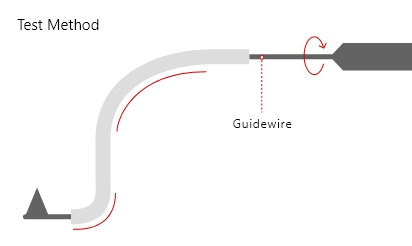
Measured by the movement of the guide wire tip when it is rotated inside a curved tube.
If the torque response is high…
- The tip has linear response when rotated
- The guide wire can be intentionally manipulated
If the torque response is low…
- Wire rotation may be done more than necessary
- Torque does not get transmitted smoothly, resulting in a sudden whip in the wire tip
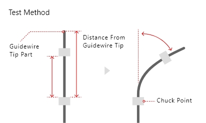
Torque force
Ability to transmit the power of rotation to the tip of the guide wire without attenuating.
Test Method
Measured by the point where the shaft becomes bent 3cm~55cm from the tip while it is kept in place.
If the torque force is high…
- The wire can be manipulated without getting trapped in the lesion
If the torque force is weak…
- There is a risk of wire breakage when it gets trapped inside the lesion and rotated in that state.
Shaft support
Test Method
Measured by the point where the shaft becomes bent 3cm~55cm from the tip while it is kept in place.
If the shaft support is high…
- It enahnces backup support of the guiding catheter
- It makes device delivery easier by stretching out the vessel
If the shaft support is low…
- The wire can be advanced without straining the vessel
Tip flexibility
The guide wire flexibility measured horizontally 3cm from the tip.
Test Method
The wire is placed in a tube, then the tip is pushed out . A fixed amount of force is applied to each measruing point attached to a sensor, and the force needed to bend the wire to a certain angle is measured.
If the tip flexibility is high…
- It is less likely to damage the vessel wall when there is contact
- It is more difficult to enter hard lesions
If the tip flexibility is low…
- There is a higher risk of damaging the vessel wall
- It is easier for the wire the keep advancing when it hits a harder lesion
Tip load
Tip load is the numerical conversion of the physician's feeling of "softer/stiffer" of the wire tip, and is calculated by its gram value.
Test Method
Measured by the force needed to bend guide wire wet with water pushed against a sensor 10mm from the tip.
Guide wires with high tip load have…
- Thick cores and high torque force
- Low in tip flexibility and tend to run straight
Guide wires with low tip load have…
- Thin cores and low torque force
- High in tip flexibility and tend to change direction according to the resistance from vessels and lesions
Tip end design
The ball tip attached to the tip of the guide wire are processed at the manufacturing sites, and contribute to perfomance in penetration force of each wire.
-
Round tip
Standard round ball-tip design. -
Micro-cone tip
The end of the ball tip is grinded to form a cone-shape, which enhances its ability to penetrate lesions. -
Blunt tip
The tip is processed to form a blunt, square-like shape which increases contact area against the lesion and resistance to the tip. In cases where the vessel route is unclear, the risk of perforation can be reduced as the wire can be advanced according to feedback from the tip.
Coil design
The O.D. of the tip of the coil. ASAHI coil forming technologies makes it possible to adjust the O.D. to fit the features of each guide wire.
-
Straight
Standard design where the coil maintains a fixed O.D. -
Tapered coil
The O.D. becomes smaller toward the tip. This design enhances the wire's ability to enter CTO lesions and select smaller routes
Lubricity
Ability to lower the resistance felt from the vessel or lesion when advancing the guide wire. The effects change according to the coating material.
Test Method
Measured by the resistance when the guide wire is pushed back and forth with a weight on it.
Three coatings
When the lubricity is high…
- It is easier to advance through tighter routes because of less resistance from the vessel and lesion.
- There is a higher possiblity of the wire tip to move unintentionally due to cardiac beating.
Torque response
The ability to quickly transmit the rotation applied at the proximal side to the tip of the wire. The quicker the rotation is transmitted to the tip, the higher the torque response.
Test Method
Measured by the movement of the guide wire tip when it is rotated inside a curved tube.
If the torque response is high…
- The tip has linear response when rotated
- The guide wire can be intentionally manipulated
If the torque response is low…
- Wire rotation may be done more than necessary
- Torque does not get transmitted smoothly, resulting in a sudden whip in the wire tip
Torque force
Ability to transmit the power of rotation to the tip of the guide wire without attenuating.
Test Method
Measured by the force transmitted to the tip of the guide wire when it is rotated while the tip is kept it place.
If the torque force is high…
- The wire can be manipulated without getting trapped in the lesion
If the torque force is weak…
- There is a risk of wire breakage when it gets trapped inside the lesion and rotated in that state.
Shaft support
Test Method
Measured by the point where the shaft becomes bent 3cm~55cm from the tip while it is kept in place.
If the shaft support is high…
- It enahnces backup support of the guiding catheter
- It makes device delivery easier by stretching out the vessel
If the shaft support is low…
- The wire can be advanced without straining the vessel
Tip flexibility
The guide wire flexibility measured horizontally 3cm from the tip.
Test Method
The wire is placed in a tube, then the tip is pushed out . A fixed amount of force is applied to each measruing point attached to a sensor, and the force needed to bend the wire to a certain angle is measured.
If the tip flexibility is high…
- It is less likely to damage the vessel wall when there is contact
- It is more difficult to enter hard lesionsい
If the tip flexibility is low…
- There is a higher risk of damaging the vessel wall
- It is easier for the wire the keep advancing when it hits a harder lesion